Tuesday, March 26, 2013

Progress Update

Things have slowed down a bit recently as school, work, and studying for the FE exam have taken priority. The leadscrew and guide rods should be cut to size this week, and more brackets are being printed.

I have been reading up on the SPI interface with arduino and it seems to be fairly straight forward. It seems as though the hardest part will be the control of the motor via computer.

The drive system is being redesigned to reduce weight on the top of the printer and to consolidate the electronics. In addition, I have Ben toying with the idea of keeping the threaded rod unconstrained on one end, and using just the two smooth rods and captured but for alignment. This would prevent the system from becoming over constrained and binding.

The container for the photo polymer and the build plate have yet to be designed. I do not think they will be too difficult, and am focusing on moving the leadscrew at the moment.

After April 13 (when I have my fundamentals of engineering exam) I hope to really pick up the pace.

Wednesday, March 13, 2013

Frame Built

The frame has been built! It seems fairly sturdy and should hold up well for this purpose. I'm not sure I would trust the 3d brackets for a long term solution only because I printed them at a lower temperature than I should. There are some layer adhesion issues that I can fix with higher extruder temperatures and lower layer heights if I want to make them again.

The brackets also took a lot of post processing work to get them to fit right. Each hole had to be drilled out, and the alignment tabs needed to be filed down. Still, they're pretty amazing considering the cost savings compared to aluminum brackets. If I had a better printer, like a DLP projector based printer, I think these brackets would work perfectly.

Monday, March 11, 2013

Printing Corner Brackets

Using Lupe, my RepRap Prusa Mendel, to print the Corner Blocks for my frame. Printing two at a time really helps to distribute the heat from the nozzle and improve print quality.

Electronics are In!

I ordered some parts last weekend from SparkFun and they've already arrived! Pictured from left to right is the Arduino UNO R3, the L6570 Stepper Driver Breakout Board, and a 68oz.-in Stepper Motor with 400 steps/revolution.


The Stepper I chose had a higher current draw than what was supported on the Easy Driver or Big Easy stepper controllers, so I had to step up (haha, step) to a bigger board. Plus, the L6570 supports up to 128 microsteps per full step. This could help theoretically increase my resolution even further.

Extrusions Cut and Tapped

The Aluminum came in last week and my coworker, Josh, helped to cut them to size. After numerous hours of watching Bob's Burgers and tapping the ends of each extrusion with an M5 tap, the frame is ready to be assembled.

Friday, March 1, 2013

Materials

I found a great site with various photopolymers available to use. I am not sure yet whether or not they are compatible with a DLP printer, but I have sent an email to find out more.

One material in particular, the ABStuff, has very similar properties to ABS. This will make it ideal for printing and prototyping. Other materials can break down in the body, some are more elastic, and others look beige and fleshy. What a world we live in.

(fleshy plastic. source:digfablab.wikispaces.com )


Projector Offset, Materials, and More


I found a great resource online that provides the dimensions of a projected image from a specified projector given various parameters of how you will set up your home theater system. I can use this information to determine where my image will be in relation to the center axis of my lens.


(projected dimensions based off of distance from screen)

The site also provided me with the official product manual and mounting hole locations on the back. The less guess work I have to do, the better!

(projector mounting hole locations)

I am now working on designing my Z axis. My current plan is to have it run on three LM8UU linear ball bearings. I will use two bearings on one side, and one on the other. This helps to lock the z axis into a plane, by fixing three points. These bearings will run on 8mm smooth polished drill rod. The 5/16"-24 nuts will be captured above and below the z axis, with a spring between the axis and the top nut. This system is also used in the RepRap Prusa x ends, and helps to prevent binding.
(Z axis concept)

I have a week off of school, and will divide my time between work and the printer. All of the components have arrived, so I just need to start building the frame.


Printing Corner brackets!

Tuesday, February 19, 2013

Frame Components Purchased


I pulled the trigger today on a McMaster-Carr order for components to build the frame.

I purchased extra T-slot nuts for work, so the final total for the printer will be less. I will factor this in later when I make the final total.

The 9mm diameter rod will be cut in half to be used as a guide rod. for the Z axis. The 5/16"-24 threaded rod will act as a lead screw to move the axis. Notice, I didn't purchase any 5/16"-24 nuts, which was a mistake.

An now time for some math:
A rod with 24 threads per inch would then need 24 revolutions to move the build plate up 1" .
The NEMA 17 stepper motor I plan to use has 400 steps per revolution.

That's 2.64583316 microns per steps!

That's a theoretical value, assuming no binding in the nuts, no play in the coupler between the motor and the threaded rod, and that the board is capable of sending commands in 1 step increments to the motor. This is also assuming I didn't screw up somewhere, as that seems to be very small. By comparison, the MakerBot Replicator 2 has a minimum 2.5 micron accuracy, while the Formlabs Form-1 has a minimum of 25 microns. When comparing the layer height, the MakerBot has a minimum of 100 microns, while the Formlabs printer still has a minimum of 25 microns. This is due to the nature of the materials used in the printing process. Since the MakerBot uses 1.75 mm  (0.069 in) filament extruded through a 0.4 mm (0.015 in) nozzle, the minimum effective layer height is now a function of the material being extruded. If it is extruded too thin, it will bulge outwards and the XY resolution will be compromised. Since the Formlabs printer uses Resin that cures via UV light, we don't have to worry about the change in width as a function of layer height. 


(source: buildyourcnc.com)


Since these calculations are very straightforward, I will experiment with rods that have different threads per inch. My goal with this printer is to increase the printer resolution, not speed. If 24 threads per inch and a slow speed get's the job done, great. 

Sunday, February 17, 2013

Frame Modeled

After testing the projector's minimum distance and image size, I began working on the frame in Solidworks.
Below is the first revision:
(REV 1 of the Frame)

The Z axis moves on two smooth rods (5/16" or 9mm if I'm lucky) and uses a 5/16 threaded rod. This setup is the same as what is used on my RepRap, and is quite reliable and can provide very small layer heights. If I want to improve my layer resolution, I can always upgrade later to ACME rod, which is designed for high precision linear motion.

(Close up of the Z axis, coupler not included yet)


Two components have been designed to be 3D printed for the frame. The first is a holder for the NEMA 17 stepper motor and smooth rods. It will be mounted on the top of the frame. 

(NEMA 17 Holder)


The second component is a bearing holder for the bottom of the smooth rod. It will help to constrain the rod and allow it to still rotate. This is based on a Z stabilizer part found on Thingiverse, and should help increase part accuracy. I will use a helicoil shaft coupler to attach the stepper motor to the threaded rod, to reduce the chance of binding. 

(608zz Bearing mount with integrated smooth rod holders)

All parts will be available on Thingiverse as soon as I can convert them to STLs.


Testing the projector image size and minimum distance

(Minimum projection area of 6 in x 4.5 in at a distance of 10.5 inches)

I am trying to use the smallest image possible from the projector in order to maximize the effective resolution of my printer. The individual pixels will be smallest when the image is smallest. This distance could theoretically be reduced by modifying the optics of the projector, but it is nice to have the projector left unmodified so I can watch more shows on my ceiling when I get bored. If I see a need to modify the optics, I can always come back to the idea later. 

Wednesday, February 13, 2013

DLP Printing pt. 3: The Frame

Now I am beginning to design the frame. The first version will be made of 20mm x 20mm aluminum T-Slot extrusion, also commonly referred to as "80-20". This material is ideal for frames and prototypes since it allows anything to be mounted along the frame, and makes it easy to move components around. In addition, it is fairly inexpensive and much more robust than threaded rod. 80-20 has been used in many RepRap printers and has proved to simplify the build, decrease build time, provide more freedom to modify, and is incredibly sturdy. AlephObjects, maker of the LulzBot AO-101 has tested their printer while standing on it, driving it off road, and making it print upside down.
 
(the profile of a 20mm x 20mm aluminum extrusion. source: eBay)

My main goal is to use as little material as possible to reduce cost and simplify building the printer. It's worth investing in a m5x0.8 mm tap to add tapped holes to the end of your extrusions. McMaster Carr sells both the extrusions and various connectors. It is worth buying the extrusion on their website, but a corner block sells for $10 each! This quickly adds up. Luckily, there's thingiverse! Printing a corner block on my RepRap prusa with 0.35mm layer height took roughly 20 minutes and cost about $0.16! 

Here are some excellent extrusion components:
Corner Block -- These work incredibly well and are ~60x cheaper than the aluminum ones for sale!
90 Degree Corner Backet -- These also work very well, although the overhang is tricky. Blowing on it worked until I got light headed.

In addition, I will be uploading all parts I make onto Thingiverse. Follow me, and make sure to print a Toothbrush holder.


DLP Printing pt. 2: The projector

The projector is the most important component to a DLP printer. DLP stands forDigital Light Processing, and is a technology developed by Texas Instruments to project light. I'm not going to go into many details about the technology, as it doesn't really matter for the printer. All that is important is that there is a filter that blocks UV light from being projected, and we need to fix that. The projector replaces both the X and Y axis of a typical FDM printer by projecting the desired layer shape onto the build plate. The projected image is black and white, and the white region is where the resin cures. A simple way to visualize this process is to think of an MRI or CATScan. An objected is "sliced" like deli meat into many thin layers. The printer recreates each layer on top of each other sequentially until the object has formed.


(LEFT: the desired shape. RIGHT: the sliced version. source: Wikipedia: Rapid Prototyping) 


After a week of eBay hunting, I came across a used Optoma EP716 DLP Projector for only $40. This projector is capable of resolutions up to 1400x1050, and has a 200W UHP (Ultra High Performance) mercury- arc bulb. It came with a working bulb, which is strangely difficult to come across on eBay, and the only thing missing was the remote. The projector arrived yesterday and is in decent condition, with only a couple of scratches. After watching an episode of Late Night with Jimmy Fallon on my ceiling while lying down, I decided it was time to get to work.


(my baby! source: eBay listing)


Key components for a good Projector:
  • MUST be DLP (a Texas Instruments technlogy. Read more about it here)
  • A high wattage lamp. The higher the wattage, the stronger the light and the faster the cure time
  • Avoid LED. These are harder to get enough UV light from. It seems as though it is possible to use a LED projector, but there will be much more work.
  • A high resolution. The build area and resolution of your prints is directly proportional to the projector resolution. The projected image is the X and Y axis, while the lead screw moving the build plate is the Z axis.

DLP Printing pt 1: The Basics


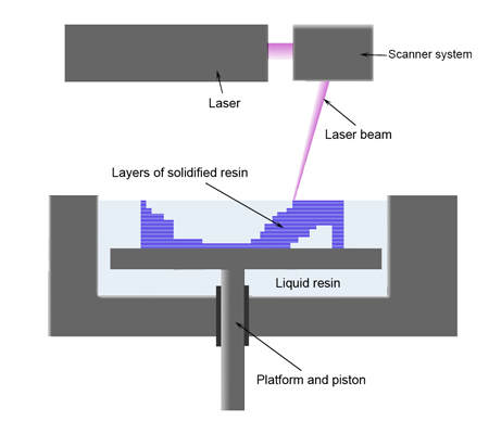
After some research, it seems as though the next step in the 3D printing revolution will be in the form of Stereolithography (SLA). This process differs in a couple key ways from PLA, and has its own benefits and downsides. SLA works by exposing a portion of a UV curable resin to light waves in the correct spectrum to selectively harden that area into plastic. 3D systems pioneered this technique in the late '80s and has been the leader in commercial grade printers since then. Only recently has it been made available to consumers. The newly announced Formlabs Form 1 printer is the first truly competitive SLA device, competing with the highest quality Fused Deposition Modeling (FDM) printers such as the MakerBot Replicator 2.

(image source: Wikipedia: Stereolithography)

Just like the RepRap, people have begun to construct their own versions of SLA printers. There are two main ways to harden the polymer: via a laser pointer, and with a projector. Lasers are harder to cool and cost much more than a projector, so most DIYers use a projector. Not any projector will work though. It seems as though DLP projectors are needed to crank out the UV light needed to cure the polymer.

Some great sources on DIY DLP projectors are below:
LemonCurry Wiki

(my attempt at making a diagram of the set up)


These have been my guides in the design of my printer. I aim to make everything freely and openly available, and will upload all parts to Thingiverse to help start a new wave of DLP printers. This is part 1 of many chronicling my build, I hope it serves to be a helpful guide. Enjoy!


Thursday, January 10, 2013

Issues and Upgrades

I have been experiencing the same couple of issues with my printer recently: a grinding Z motor, slanted prints, and trouble grabbing my filament with the hobbed bolt.

 After multiple hours of experimenting with the stepper current, re-leveling my print bed and X axis, and completely reassembling my Z axis, I discovered the culprit for the slanted prints. My Y axis pulley was rubbing against the face of my stepper motor, causing it to progressively miss steps. In addition, my motor was not secured tightly to the motor mount, allowing it to move around. Immediately, I noticed significantly straighter prints.

The grinding in my z steppers was due to the rod couplers used to connect the motors to the 5/16" threaded rods used as lead screws. I had tightened my motors to the frame, and used an unforgiving coupler, which essentially guaranteed that my rods were not coaxial with the motor shaft. After removing the screws, my motors sit loosely in their holders and I have yet to hear another grinding sound in 2 weeks.

The filament issue is mostly due to laziness on my part. I need to find metric hardware, but it is expensive and hard to find. It works consistently enough to be a small annoyance instead of a big deal. Print quality is usually excellent, and the other fastener would only make loading new filament easier.

I ordered a GT2 belt and pulley set to replace the T5's on my X and Y axis. The print quality seems to have improved a bit, and I am worried less about skipping. Following some advice I stumbled across online, I twisted the X belt 180 degrees so that the smooth portion of the belt runs on the idler instead of the teeth. This should help to remove any artifacts in the X direction of my prints.


Introduction

I began building a RepRap Prusa Mendel about a year ago after an impulse buy on eBay. I ordered a kit of pre cut 5/16" Threaded rods and hardware necessary to begin the construction of my printer. I spent months researching the various options and eventually settled on the Prusa due to it's ease of construction and available modifications.

My current set up is as follows:
  • Gen 6 electronics
  • Optical Endstops
  • Lulzbot Buddaschnozzle 1.0 hot end
  • Wades accessable extruder
My Prusa uses the following upgrades over the "stock" configuration:

  • LM8UU linear bearings on the X and Y axis
  • Glass Print Bed
  • Z Rod Constraints